Hollow nanoparticles for the oxygen reduction reaction
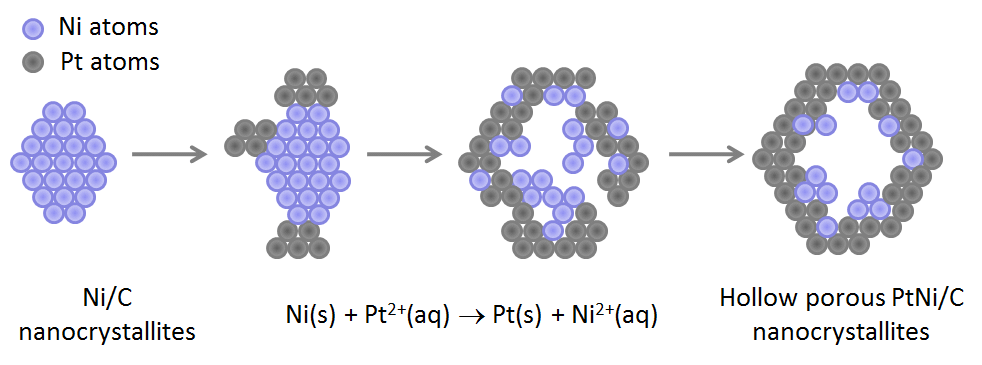
Pt hollow particles were initially “discovered” from the degradation of Pt3Co/C alloys in PEMFC on-site operation 1-3. Knowing the potentially enhanced ORR activity of such structures, we decided to elaborate on purpose a set of Pt hollow nanoparticles and to study their ORR activity and durability in PEMFC environment. In a typical synthesis, Pt(NH3)4Cl2.(H2O), NiCl2.(6 H2O) and NaBH4 are mixed with Vulcan XC72R®, ethanol and de-ionized water following the protocol first described by Bae et al. 4. Based on recent results from Shan et al. 5, Ni–B/C compounds are believed to form first, therefore acting as sacrificial templates for the deposition of Pt atoms via galvanic replacement (Figure 1). The deposition of Pt atoms proceeds on preferential regions of the sacrificial Ni-rich/C nanoparticles yielding nanometre-sized PtNi/C clusters, which grow in close proximity to each other, and coalesce as the reduction of Pt2+ ions proceeds.

Figure 1. Schematic illustration of the procedure used to synthesize hollow Pt-rich nanoparticles.
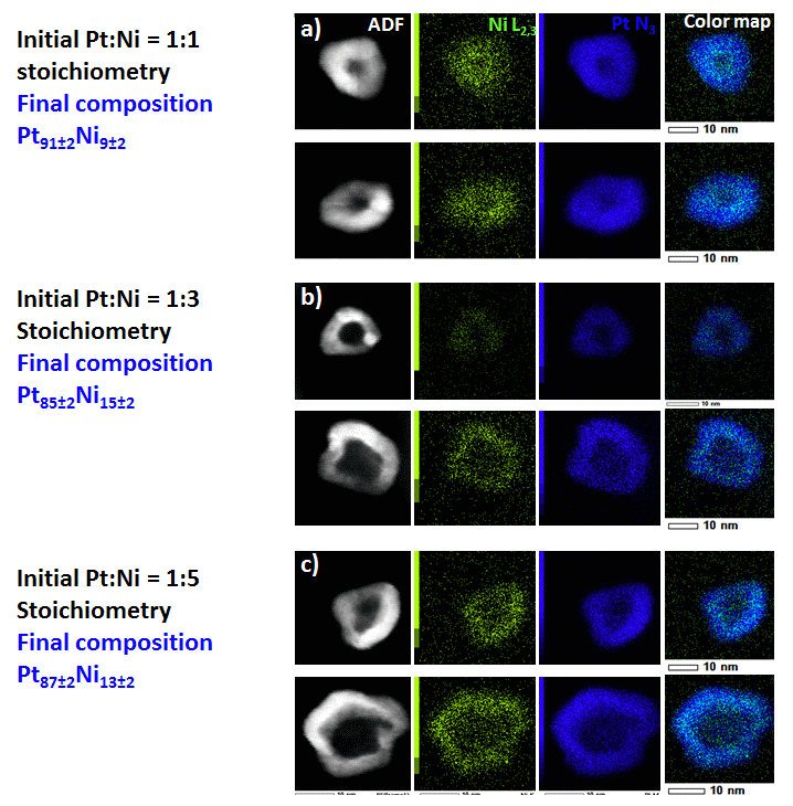
Figure 2 displays HAADF-STEM images, line-scan analysis and X-EDS elemental maps of hollow PtNi/C nanoparticles synthesized by varying the Pt:Ni atomic ratio in the initial metal salt precursor solution from 1:1 to 1:5. The PtNi/C nanoparticles feature irregular shape, and sizes comprised between ca. 10 and 15 nm. Their central portion is darker than their surface, therefore confirming a hollow nanostructure. The electrocatalysts feature contracted lattice parameter, and contain little residual Ni atoms inside their lattice (< 10-15 at. %), thus avoiding subsequent contamination of the ionic conductors contained in a PEMFC environment (proton exchange membrane/ionomer) 6.

Figure 2. (a, b, c). HAADF-STEM images, line scan analysis and X-EDS elemental maps of hollow PtNi/C nanoparticles. The Pt:Ni stoichiometry in the initial metal salt precursor solution was (a) 1:1, (b) 1:3 and (c) 1:5.
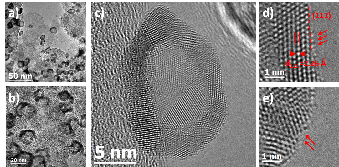
Aberration-correction HR-TEM images revealed atomic details out of reach for conventional microscopes. For example, in Figure 3a, a discontinuity of the PtNi shell is evidenced in the centre of the nanoparticle. Fourier transform (FT) analyses of the HR-TEM image in the centre of the particle (red square zone) and in the metal shell (yellow square zone) are shown in insets (top-right and bottom-right, respectively). In the centre of the nanoparticle, the FT pattern is structureless due to the absence of metal in the corresponding zone. In the metal shell, the FT pattern shows the presence of (111) lattice reflections from PtNi. These results provide clear evidences that a fraction of the hollow PtNi/C nanocatalysts is nanoporous.

Figure 3. Aberration corrected HR-TEM images of the hollow PtNi (1:3)/C nanoparticles. (a) and (b) assemblies of PtNi (1:3)/C nanoparticles imaged at 250 and 400 kX nominal magnification respectively. (c) a HR-TEM image of a single PtNi (1:3)/C nanoparticle. Zoom-in images at the particle surface are shown in (d) and (e). Arrows are used to highlight different structural defects.
The best porous hollow PtNi/C nanocatalysts achieved 6-fold and 9-fold enhancement in mass and specific activity for the ORR, respectively over standard solid Pt/C nanocrystallites of the same size 7. The catalytic enhancement was 4-fold and 3-fold in mass and specific activity, respectively over solid PtNi/C nanocrystallites with similar chemical composition, Pt lattice contraction and crystallite size. Furthermore, 100 % of the initial mass activity at E = 0.90 V vs. RHE (0.56 A mg-1Pt) of the best electrocatalyst was retained after an accelerated stress test composed of 30 k potential cycles between 0.60 and 1.00 V vs. RHE (0.1 M HClO4 – T = 298 K). The better catalytic activity for the ORR of porous hollow PtNi/C nanocatalysts is ascribed to (i) their opened porosity, (ii) their preferential crystallographic orientation (“ensemble effect”), and (iii) the weakened oxygen binding energy induced by the contracted Pt lattice parameter (“strain effect”).
Pt hollow particles were initially “discovered” from the degradation of Pt3Co/C alloys in PEMFC on-site operation 1-3. Knowing the potentially enhanced ORR activity of such structures, we decided to elaborate on purpose a set of Pt hollow nanoparticles and to study their ORR activity and durability in PEMFC environment. In a typical synthesis, Pt(NH3)4Cl2.(H2O), NiCl2.(6 H2O) and NaBH4 are mixed with Vulcan XC72R®, ethanol and de-ionized water following the protocol first described by Bae et al. 4. Based on recent results from Shan et al. 5, Ni–B/C compounds are believed to form first, therefore acting as sacrificial templates for the deposition of Pt atoms via galvanic replacement (Figure 1). The deposition of Pt atoms proceeds on preferential regions of the sacrificial Ni-rich/C nanoparticles yielding nanometre-sized PtNi/C clusters, which grow in close proximity to each other, and coalesce as the reduction of Pt2+ ions proceeds.

Figure 1. Schematic illustration of the procedure used to synthesize hollow Pt-rich nanoparticles.
Figure 2 displays HAADF-STEM images, line-scan analysis and X-EDS elemental maps of hollow PtNi/C nanoparticles synthesized by varying the Pt:Ni atomic ratio in the initial metal salt precursor solution from 1:1 to 1:5. The PtNi/C nanoparticles feature irregular shape, and sizes comprised between ca. 10 and 15 nm. Their central portion is darker than their surface, therefore confirming a hollow nanostructure. The electrocatalysts feature contracted lattice parameter, and contain little residual Ni atoms inside their lattice (< 10-15 at. %), thus avoiding subsequent contamination of the ionic conductors contained in a PEMFC environment (proton exchange membrane/ionomer) 6.

Figure 2. (a, b, c). HAADF-STEM images, line scan analysis and X-EDS elemental maps of hollow PtNi/C nanoparticles. The Pt:Ni stoichiometry in the initial metal salt precursor solution was (a) 1:1, (b) 1:3 and (c) 1:5.
Aberration-correction HR-TEM images revealed atomic details out of reach for conventional microscopes. For example, in Figure 3a, a discontinuity of the PtNi shell is evidenced in the centre of the nanoparticle. Fourier transform (FT) analyses of the HR-TEM image in the centre of the particle (red square zone) and in the metal shell (yellow square zone) are shown in insets (top-right and bottom-right, respectively). In the centre of the nanoparticle, the FT pattern is structureless due to the absence of metal in the corresponding zone. In the metal shell, the FT pattern shows the presence of (111) lattice reflections from PtNi. These results provide clear evidences that a fraction of the hollow PtNi/C nanocatalysts is nanoporous.

Figure 3. Aberration corrected HR-TEM images of the hollow PtNi (1:3)/C nanoparticles. (a) and (b) assemblies of PtNi (1:3)/C nanoparticles imaged at 250 and 400 kX nominal magnification respectively. (c) a HR-TEM image of a single PtNi (1:3)/C nanoparticle. Zoom-in images at the particle surface are shown in (d) and (e). Arrows are used to highlight different structural defects.
The best porous hollow PtNi/C nanocatalysts achieved 6-fold and 9-fold enhancement in mass and specific activity for the ORR, respectively over standard solid Pt/C nanocrystallites of the same size 7. The catalytic enhancement was 4-fold and 3-fold in mass and specific activity, respectively over solid PtNi/C nanocrystallites with similar chemical composition, Pt lattice contraction and crystallite size. Furthermore, 100 % of the initial mass activity at E = 0.90 V vs. RHE (0.56 A mg-1Pt) of the best electrocatalyst was retained after an accelerated stress test composed of 30 k potential cycles between 0.60 and 1.00 V vs. RHE (0.1 M HClO4 – T = 298 K). The better catalytic activity for the ORR of porous hollow PtNi/C nanocatalysts is ascribed to (i) their opened porosity, (ii) their preferential crystallographic orientation (“ensemble effect”), and (iii) the weakened oxygen binding energy induced by the contracted Pt lattice parameter (“strain effect”).
Acknowledgements
This work is performed within the framework of the Centre of Excellence of Multifunctional Architectured Materials "CEMAM" n° AN-10-LABX-44-01 funded by the "Investments for the Future" program. The authors acknowledge financial support from University of Grenoble-Alpes through the AGIR program (grant number LL1492017G), and from the French National Research Agency through the HOLLOW project (grant number ANR-14-CE05-0003-01).
References
1. Dubau, L.; Durst, J.; Maillard, F.; Guétaz, L.; Chatenet, M.; André, J.; Rossinot, E., Electrochim. Acta 2011, 56, 10658-10667.
2. Dubau, L.; Lopez-Haro, M.; Castanheira, L.; Durst, J.; Chatenet, M.; Bayle-Guillemaud, P.; Guétaz, L.; Caqué, N.; Rossinot, E.; Maillard, F., Appl. Catal. B 2013, 142-143, 801-808.
3. Lopez-Haro, M.; Dubau, L.; Guétaz, L.; Bayle-Guillemaud, P.; Chatenet, M.; André, J.; Caqué, N.; Rossinot, E.; Maillard, F., Appl. Catal. B 2014, 152-153, 300-308.
4. Bae, S. J.; Yoo, S. J.; Lim, Y.; Kim, S.; Lim, Y.; Choi, J.; Nahm, K. S.; Hwang, S. J.; Lim, T. H.; Kim, S. K.; Kim, P., J. Mater. Chem. 2012, 22, 8820.
5. Shan, A.; Chen, Z.; Li, B.; Chen, C.; Wang, R., J. Mater. Chem. A 2015, 3, 1031-1036.
6. Durst, J.; Chatenet, M.; Maillard, F., Phys. Chem. Chem. Phys. 2012, 14, 13000-13009.
7. Dubau, L.; Asset, T.; Chattot, R.; Bonnaud, C.; Vanpeene, V.; Nelayah, J.; Maillard, F., ACS Catal. 2015, 5, 5333-5341.


